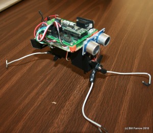
At the Triangle Robotics Club meeting this month (July 2010) we went over the three common types of motors and discussed how to control them.
A number of people brought in projects for a quick show and tell. Tonight we had working examples showing each type of motor and it’s controller circuit. This was a great way to kick off the nights discussion on basic motor control theory.

The great thing about the robotics clubs is that we have many experienced and knowledgeable members who are willing to help.
Field Effect Transistors (FET)
- FETs are better than transistors for controlling motors
- FETs typically have built in protection diodes
- FETs are more easily controlled directly from Microcontroller GPIO pins
- FETs that switch current on and off don’t generate too much heat
- FETs don’t have a voltage drop like transistors do
Back EMF
- Transistors used to drive motors require an additional protection diode
- Motors generate large back-emf voltages when they move under inertia (when you turn off the current and the motor keeps spinning)
DC Motors
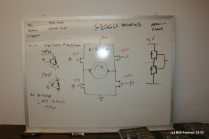
- DC Motor forward and reverse control using an H-Bridge circuit
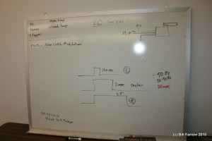
- Use PWM to control motor speed
- Active motor breaking to stop motor rotation using the H-Bridge
H-Bridges can be built from descrete components (4x FETs) and are also available in a single package.

RC Servos
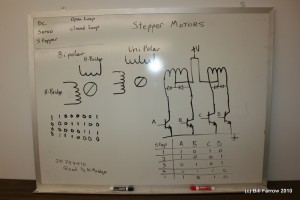
Stepper Motors
Stepper motors are used because they have high torque, discrete step positions, and will not be damaged if externally forced to rotate (no gears to strip). The downside is that they require current at all times to maintain an accurate position, which is not ideal for battery powered robots.

